1999 Ford Ranger a/c Stops Cooling Going Down the Road
Its summer and your A/C does not piece of work. That sucks. Well, I accept the write up to help yous get it back on the road. Keep in heed, my write up only covers 134a systems, specifically in the 1997 4.0 OHV configuration. I believe that 94+ Rangers were outfitted with R134a, but 94 was a transition twelvemonth, so you might accept either R12 or R134a for that year. The overall advice given will employ to other engines and years as well, simply you might have to make some adjustments mechanically.
Difficulty: 9 Out of ten Wrenches:
The reason I am putting this so high is that you actually need to pay attending to details. Miss a detail and yous tin can have all of your work exist for nothing, including trashing a very expensive compressor. Some other difficulty is that messing with the refrigerant cans is dangerous. If you open the wrong valves on the manifold gauge set you can cause the can to explode, peradventure severely injuring yourself or any bystanders. As well, keep in heed that the different years of Rangers use different amounts of refrigerant. The 97 has 25 ounces which is a pilus over two 12 ounce cans, where the 94 uses 28 ounces (although I take seen 36 ounces for the 94 every bit well, but I believe that might be for the R12 version) the 1999 uses xxx ounces. This information will also exist displayed on the sticker that is on height of the radiator support. Go with that amount if the sticker is still in that location and readable. I highly recommend that y'all read this How-To in its entirety earlier you lot showtime the repair, and make certain that you sympathise each step and what and why you are doing it. If you are unsure of something, ask someone who is knowledgeable, or accept your truck to a shop.
Before Job Preparations:
Remove children, small animals, anyone with sensitive ears and anyone else that y'all do not desire to be a target of your frustration and anger toward the Ford engineers that designed this cussing mess�
Disclaimer:
The Ranger Station.com, The Ranger Station.com Staff, nor the original poster are responsible for you doing this modification to your vehicle. By doing this modification and following this how-to you, the installer, accept total responsibility if anything is damaged or messed up. If y'all accept questions, feel free to PM the original affiche or ask in the advisable section of The Ranger Station.com forums.
Lets Look at How Your A/C Works:
Before we become to the testing and repair, let�s look briefly at how an air conditioner works. An air conditioner has 5 main parts: The compressor, Evaporator (in the heater box) Condenser (in front of the radiator), Accumulator/dryer (right side by side to the heater box in the engine compartment) and expansion valve or orifice tube. The engine is what runs the compressor. If at that place is plenty static pressure (the pressure in the system when the A/C is not running) which is over 75 psi, and the electromagnetic clutch is working, when you turn on the A/C, the clutch will appoint the compressor which pressurizes the Refrigerant gas. This in turn makes the Refrigerant gas very hot (basic thermodynamics). This hot Refrigerant then goes into the condenser which extracts the heat from the refrigerant using the trucks radiator fan or as the air goes across the condenser when the truck is moving, causing the Refrigerant to condense into a liquid. Afterwards the liquid Refrigerant exits the condenser, it goes through the expansion valve or orifice tube into the Low-Pressure level side of the organization where the Refrigerant starts humid speedily as it goes into the evaporator. This humid causes the liquid Refrigerant within the evaporator to become very cold equally it turns dorsum into a gas (again, basic thermodynamics), and a fan blows over the evaporator which cools the air and because libation air as well cannot hold equally much wet, causes the moisture in the air to condense into water which lowers the humidity of the air as well. Afterwards the evaporator the Refrigerant gas goes into the accumulator/dryer. The accumulator/dryer holds excess PAG oil, removes any wet in the refrigerant using a desiccant and catches any liquid refrigerant that has not boiled into gas yet (Liquid refrigerant going into the compressor will hydro lock it, just similar taking h2o in the intake of the truck). The gas and then returns to the compressor to commencement the cycle all once more. The compressor clutch is controlled past the employ of the pressure transducer switches. If the pressure gets as well high, the High side transducer (located on the manifold bolted to the dorsum of the compressor) will open and not allow the power to the clutch until the force per unit area drops back downwardly. The pressure switch transducer which is located on the accumulator/ dryer is open if there is not enough static pressure. If there is enough static pressure, the clutch will engage. You may at present wake up, the slow lecture is over.
*Note For Those Doing a R12 to R134a Retrofit:
You will need to replace your hoses, o-rings, and all of the oil. Y'all want to exist very careful of what oil you employ, every bit some will not be compatible with the old mineral oil that the R12 systems use! I will not cover retrofitting in this walk through in detail. Besides notation, if your truck is not a 97, research the capacities for the oil and refrigerant earlier starting, and make adjustments to these instructions to fit your detail truck.
A discussion or two about Refrigerants and Oils: I am only doing this walk through for the 94+ trucks that have the R134a refrigerant. If you are looking to do a retrofit as R12 is now illegal to buy or sell, (at to the lowest degree for the boilerplate consumer that does not have a proper license to buy and sell R12) yous volition want to do some more than inquiry on what parts you need to supplant and how much refrigerant to utilize, what type of oil to use etc. R134a is a fairly inexpensive refrigerant. You can go it at merely about any department store or automotive store from near 7 to x dollars for a 12 oz tin can. Do non use anything but R134a, equally other refrigerants tin can be incompatible with the oil and cause a big mess. Plus, any motorcar that has a refrigerant alloy or any weird or exotic refrigerants will non be touched by any mechanic as the recovery procedure volition contaminate his motorcar and supply of R134a. It is likewise illegal to knowingly vent the refrigerant into the atmosphere. Information technology must be recovered past a qualified person who has the recovery equipment.
For oil, Ford uses PAG 46 in most of its R134a systems. I recommend getting the Double End Capped PAG 46, as it has much better lubricating qualities than regular PAG 46, plus the Double End Capped PAG oil does not absorb moisture. PAG 100 or PAG 150 are also thick. It is not very much more expensive, and for what you are paying to supercede the compressor if getting new, it is worth the 2 or 3 bucks actress. I also got some special oil for the o-rings and fittings called Nylog. It is specifically designed to keep the o-rings pliable and forbid leaks.


A Quick Tip:
Before doing any work on the A/C, make sure all electrical connections (connector at the compressor, and the connector at the pressure switches), fuses and relays are adept. Likewise check the blend doors in the nuance, every bit this is a trouble spot for the Ranger. If whatsoever of these are bad, the A/C will non come on or will not work right. Also make sure the belt tensioner is working properly. Check the condenser to see if the fins demand cleaning and / or straightening. If your condenser has all of the fins bent over you lot will have reduced airflow through the condenser and that will decrease the effectiveness of your A/C. You can get a fin comb from Harbor Freight for 5 bucks.
Tools:
You will demand access to some special tools for this fix. You will need an A/C manifold approximate ready, and a vacuum pump to evacuate the system. Yous tin buy the manifold gauge prepare at AutoZone or O�Reilly for most $90 or Harbor Freight for about $50. The pump is quite abit more expensive. I recommend borrowing or renting i for this, merely Craigslist tin can be a source too. I picked mine up on Craigslist for $35. Another option is the Harbor Freight vacuum pump that hooks up to your shop air compressor. This is but $20, but it volition not pull a deep vacuum like a regular vacuum pump fabricated for refrigeration will. *note, if using the Harbor freight vacuum pump that attaches to your air compressor, make sure your compressor can maintain at least 110 psi continually for the fourth dimension that you are using it. Virtually home compressors do not take this capacity, and then if you do not accept a commercial compressor, you might exist amend off buying a used a/c vacuum pump. Too running an air compressor for an extended period of fourth dimension will eat a lot of electricity, then be enlightened of that when you get your energy bill. If you are doing the air compressor vacuum road, I also recommend starting and warming the truck up before pulling the vacuum. The residual heat from the engine volition aid boil out the moisture at a much faster rate. If you warm upward the truck before pulling the vacuum you lot can shorten the amount of time with the vacuum pump turned on. An hour or so should do the trick. (Thanks 4x4 Junkie!)
Other Tools Needed:
� 27mm wrench
� 22mm wrench
� 13mm socket and ratchet
� 11mm deep well socket
� 10mm wrench
� 8mm wrench
� A/C � Fuel line disconnect tools (three dissimilar sizes)
� Digital Thermometer
� Feeler approximate set
� A pick to assist remove former o-rings and springlocks
� Orifice Tube Puller
� A/C flush kit which has a bottle that can exist pressurized with flush solvent and air and a hose and spray gun. I bought this off of Amazon for virtually $45
� Four Seasons Dura Two Flush Solvent � Expensive at $32 a quart, but this stuff is the best flush chemical compound y'all can get. You tin can too employ Turpentine equally a flush. I bought a quart of Turpentine to do the initial make clean and affluent, and and so used the Four Seasons stuff every bit the final flush.
� A length of hose that fits over the evaporator outlet and condenser outlet to direct the affluent solvent into a catch can.
� Grab can for the flush solvent.
I am going to write this in sections. Each department volition be devoted to a specific part that is beingness replaced. This way you can go to the department yous need to fix a specific surface area of the air conditioning arrangement. At the stop will be the Appendixes that volition requite yous some troubleshooting tips and how to flush and charge the system.
For the component replacement sections continue this important fact in heed: If y'all practice any component replacement other than the pressure transducer switches or the clutch, (ie opening the system) you will demand to replace the accumulator/dryer. If you open the arrangement to the air for more than a few minutes y'all must replace the accumulator/dryer. In fact, on a very boiling twenty-four hours, a brand new accumulator/ dryer tin can fill with moisture in as little equally 15 minutes, rendering the desiccant inside useless. If your organisation is adept, just all of the Refrigerant has leaked out, you must replace the accumulator/dryer. The reason for this is that the accumulator/dryer is what removes moisture from the Refrigerant. This prevents ice or the water from forming an acidic compound within your A/C lines and trashing your compressor/ condenser/ evaporator. The good news is that this accumulator/dryer is only about $25 at AutoZone.
Parts:
I bought nigh of my parts from Rockauto.com. Overall, I spent about $500 in parts. I basically replaced everything but the evaporator, condenser, and the pressure switches. If you are opening the system for whatever reason, you volition need to supplant the accumulator/ dryer and the orifice tube. Another rule of thumb, if you lot unhook something with an o-band, replace the o-band before you put it back together. They are inexpensive, and it would suck to have to pull the unit apart again after you lot get it dorsum together and charged up only to observe the onetime o-rings are bad. If you lot are replacing the compressor, to have the warranty honored, yous volition take to testify proof of purchase of an accumulator/ dryer, orifice tube, and condenser or have the one-time condenser flushed. It only takes a few teaspoons of the gunk from the old compressor that is in the lines to wreck the new compressor.
For the cheap minded, I recommend the local junkyard, particularly those of you lot who take access to a u pull yard. I picked upwardly a compressor for under 20 dollars with a 30 day warranty at the local Pull A Part in Indy for my 94 Intrepid a few years ago. The automobile that y'all yank your parts from should have no serious front damage, and I would go a part from a motorcar that has some refrigerant charge left in it. This will tell you the system is intact. For compressors, brand certain that the pulley spins freely and that you tin turn the compressor with a good firm grip on the hub of the pulley. You will hear it pumping and it should have a piddling resistance or stiffness in information technology. What not to get in the yard? The accumulator/dryer and orifice tube. The accumulator/dryer is $25 at AutoZone and the orifice tube is 2 bucks. Both need to be replaced with new anytime you open the system.
Here is the listing of parts that I bought to get my Ranger ice common cold again:
� Compressor
� Accumulator/ dryer
� Orifice tube
� Refrigerant Line � suction and high pressure with High pressure level port (large one that goes from the compressor around the dorsum of the engine to the top of the accumulator/ dryer)
� Refrigerant line � liquid (little ane from the condenser to the evaporator)
� O-ring kit (all the new parts that I bought had new o-rings/ springlocks installed, just in case I messed one up�)
At present For The Work.
� Section i � Pressure switches
� Section two � Electromagnetic clutch and pulley
� Section iii � Accumulator/ Dryer
� Section 4 � Orifice tube
� Department v � Compressor
� Section 6 � Large refrigerant line (suction and high side port from compressor to accumulator/ dryer)
� Section seven � Pocket-size refrigerant line (liquid � from condenser to evaporator)
� Section viii � Condenser
� Appendix A � Flushing the arrangement
� Appendix B � Prepping a new organisation for a accuse
� Appendix C � Charging the system
� Appendix D � Troubleshooting
� Appendix Due east � Sources
Parts replacement:
The first thing yous demand to do in all instances except replacing the force per unit area transducer switch and replacing the electromagnetic clutch is to take the arrangement evacuated of refrigerant. Recollect, information technology is illegal to knowingly vent whatsoever refrigerant into the temper, so if at that place is a accuse left in the system, have it properly reclaimed.
Department i
Part to be replaced:
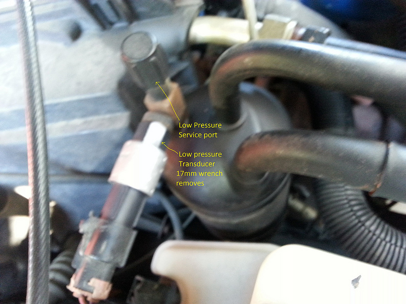
Pressure level switch transducer (Loftier and Low).
Located on the accumulator/dryer for the low pressure transducer, and correct off of the back of the compressor for the High pressure transducer. These parts can be easily accessed from the top of the engine and removed with an advisable size wrench. These are ane of two parts in this department that yous do non demand to evacuate the system to replace. You demand to unplug the wire harness from information technology and you lot will demand a 17mm open end wrench to remove the low pressure transducer and a 14mm open end wrench to remove the high force per unit area transducer. Both transducers have an o-ring, be sure to supersede the o-ring and coat it with Nylog or PAG oil before putting the new transducer on.
Section 2
Part to be replaced: Electromagnetic clutch.
This is the other part that does not require evacuating the organization.
Tools yous will need:
� Safety spectacles
� 8mm socket or wrench
� 13mm socket
� Flat blade screwdriver
� Ratchet
� Fix of feeler gauges
� 15mm combination wrench
� Torque wrench
� Snap ring pliers
� Plastic or soft face hammer
� Three jaw puller or A/C clutch tool
Procedure:
ane. If you are replacing the bearing only, hither is the role number from the OEM ford begetting: Nachi 30BG05S5DS
2. Remove the serpentine belt. This is done by placing a three/8� breaker bar in the tensioner (located in the centre of the engine) and using information technology to have the tension off of the belt.
3. Disconnect the wire to the electromagnetic clutch.
4. Remove the middle bolt from the hub of the clutch associates (viii mm) you will take to snap the wrench or ratchet chop-chop to proceed the compressor shaft from turning while doing this. You can also get a spanner wrench to hold the compressor from turning.
5. Gently tap the screwdriver between the clutch plate and pulley with the hammer at several intervals around the clutch plate to remove the clutch plate and shim(s).
6. Remove the pulley and bearing assembly past removing the snap ring property it on.
7. You will also demand a three jaw puller or clutch puller tool to aid in removing the pulley associates. Be careful when setting the jaw on the puller so that yous do not damage the electrical connector to the roll. For replacing the bearing, you can remove just the caster and not the coil if y'all fix the jaws out far enough to just grip the pulley, only the roll is likewise pressed onto the shaft and will need a puller to remove. The coil is really pressed in difficult and will demand quite a bit of work to pull off. I do not recommend removing the coil if you just need to replace the pulley, bearing or clutch plate.
8. If there is oil all over the clutch from the compressor shaft, your life just got uglier. Meet replacing of compressor below. (Y'all technically do non take to supersede the compressor, just the seal to the shaft. And that requires removing the compressor�)
nine. To install the clutch, if using the same clutch, installation is the contrary of removal. Be certain to marshal the socket for the power connector in the coil so that it is on elevation of the connector and sitting in the notch of the compressor housing. You will need to press the coil onto the shaft. A large socket volition assist seat the coil. Use the rubber hammer to set the pulley dorsum on the shaft.
ten. Installing a new clutch assembly or pulley will crave y'all to set the movement distance (air gap) between the plate and the caster face when the clutch is energized. This movement distance must be between .013� and .033� every bit measured with a feeler gauge.
eleven. If the distance betwixt the clutch plate and pulley is outside of the minimum and maximum clearances, you volition need to add or remove shims to get information technology into spec.
12. Torque the center bolt to 12 ft. lbs.


For the remainder of these parts, you lot will need to evacuate the system and replace the accumulator/dryer as well. To evacuate a charged system, take the car to a shop and take them repossess the refrigerant as it is illegal, immoral, and probably fattening to vent information technology into the air. If you do not have any charge to the arrangement, all the easier for you :p Whatever you practice, make sure that yous do non try *any* of the below repairs until y'all are absolutely 100% sure that the system has no charge or pressure in it!! And ever wear safety spectacles when dealing with the A/C system!
Department 3.
Part to exist replaced: Accumulator/ dryer
Located by the heater box on the passenger side
Tools and parts needed:
� Safety glasses
� A/C � Fuel line disconnect tool
� 27mm Combination wrench
� 22mm Combination wrench
� 8mm wrench or socket/ ratchet
� Bottle of PAG 46 Dec oil
� Nylog
� PB blaster
Procedure:
1. Remove the low force per unit area transducer switch (see Section 1 for details)
2. Soak the nut that is attached to the top tube of the evaporator with Pb blaster. Look a few minutes and soak it again. When you think you accept let it soak in enough that you can break it loose, grab the can of Lead blaster and hit it again. You might need to repeat this process a few times�
3. Use the 27mm wrench on the nut from the evaporator and the 22mm wrench on the nut for the accumulator. The nut on the accumulator is function of the tube and does *not* turn. It is at that place so you do not twist the tubing when tightening the nut from the evaporator. Turn the evaporator nut clockwise (as viewed from the front of the truck looking at the firewall. This was a reaaaly tight nut on my truck, with some of the threads showing a off-white corporeality of rust on the accumulator.
4. Y'all may still need to echo step one to get footstep 2 to piece of work�
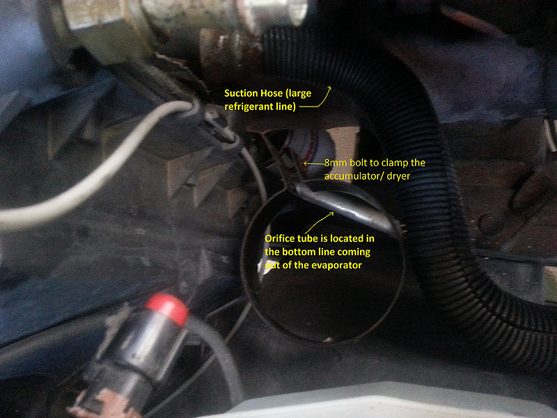
5. Disconnect the large refrigerant line from the other side of the accumulator. (This is the line that goes around the back of the engine and then comes underneath the radiator hose and curls in a �U� upward to the accumulator.) Yous will need the largest disconnect tool (white) to unhook this line. Before you put the disconnect tool on, you will need to remove the metal keeper. This can exist removed past using your easily or a gentle pry with a small screw driver. They simply slide off of the connexion point. It will take a scrap to muscle the hose off of the accumulator/ dryer every bit the o-rings volition hold it on pretty tight.
vi. Take your 8mm wrench/ socket and remove the 8 mm commodities that holds the bracket to the bottom line coming out of the evaporator. The bracket volition swing down out of the manner.
7. Accept the 8mm wrench/ socket and loosen (you do not need to remove information technology completely) several turns the commodities that holds the clamp effectually the accumulator dryer.
8. Slide the accumulator/ dryer up and out of the truck. Make sure your new accumulator/ dryer matches the old one.
9. Cascade as much oil out of the old accumulator/ dryer equally you tin can into a container. Y'all will need to put in at least this much new PAG oil into the new Accumulator/ Dryer
10. When you are ready to put the new 1 in (think, this is the last step you lot desire to do before sealing and refilling the arrangement so do not break the seals on the new unit until you are ready to seal information technology up and fill the system) be certain that it has all new o-rings and coat them with Nylog or PAG oil. There will be two o-rings at the evaporator stop and ii o-rings at the refrigerant line cease, plus one o-ring for the depression pressure level transducer.

Department iv.
Office to be replaced: Orifice tube
Located in the lower tube coming out of the Evaporator cadre.
Tools and parts yous volition need:
� Safety Glasses
� A/C � Fuel line disconnect tool
� Orifice tube removal tool
� Bottle of PAG 46 December oil
� Nylog
� New Orifice tube
� New Accumulator/ Dryer
Procedure:
1. Remove Accumulator/ Dryer (see section 3 for details)
ii. Remove the metal keeper and use the second smallest A/C line disconnect tool (blue) and disconnect the brusque refrigerant line from the bottom line of the evaporator.
iii. Use the Orifice tube tool to extract the orifice tube. Y'all tin can also use a pair of needle nose pliers instead of the Orifice tube tool, but I could not get a grip on the orifice tube with the pliers I had, so rather than fight it for 2 hours, I went and bought the damn orifice tube tool. Made my life much easier��* Protip: Compressed air tin be used to accident the orifice tube out if it is being stubborn. (wish I would have thought of that�Over again cheers 4x4 Junkie for that helpful tip)
4. Make sure your new orifice tube matches the old, and pitch the old tube. Don�t bother trying to clean and reuse information technology, they are only $2.00, it isn�t worth it.
v. Be sure to put some PAG Oil on the o-rings of the new Orifice tube
6. Replace the o-rings and put Nylog or PAG Oil on them when hooking the line dorsum up.

Section 5.
Function to be replaced: Compressor.
Located at the height of the engine on the driver side.
Tools and parts you lot volition demand:
� Safety glasses
� 3/8� breaker bar
� �� apartment blade screwdriver
� 13mm socket
� 8mm combination wrench
� 10mm combination wrench
� Ratchet
� Torque wrench
� Bottle of PAG 46 DEC oil
� Nylog
� New compressor
� New Orifice Tube
� New Accumulator /dryer
Procedure:
i. Disconnect the battery using the 8mm wrench.
2. Remove the safety air intake pipe from the upper intake and remove the air filter box. You can exit the end that is attached to the inner fender in the truck. You will demand to unhook a few sensors to exercise this. The pipe is clamped to the upper intake with a regular worm screw hose clamp. Employ the screwdriver to loosen information technology several turns, and it will slide off. The air cleaner stop has a spring clamp. Just undo it.
3. Remove the serpentine belt. This is done by inserting the 3/8� breaker bar into the square hole on the tensioner. Move the tensioner plenty to sideslip the chugalug off of the idler pulley in the center of the chugalug path. Then remove the chugalug from the compressor. The tensioner is located just below the alternator on the passenger side.
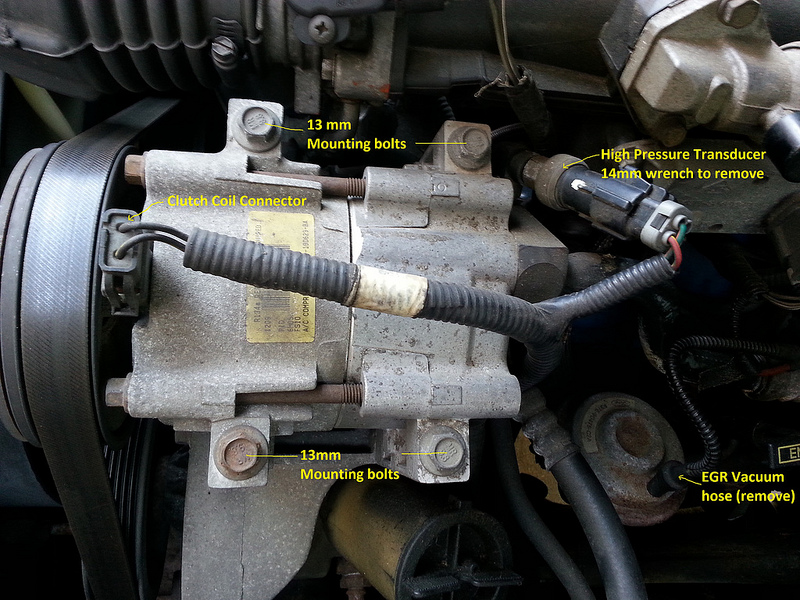
iv. Disconnect the connector to the electromagnetic clutch.
5. Unbolt the refrigerant lines using a x mm wrench. Pull the lines out of the compressor and set aside. This bolt is kind of difficult to go to as the refrigerant lines and the intake manifold block like shooting fish in a barrel access to it. You can break it loose and so by unbolting the compressor from the truck will go far easier to spin out.
half-dozen. Remove the iv 13mm bolts holding the compressor onto the bracket.
7. The compressor should be gratuitous now to take out of the engine.
8. You will now demand to clean/ purge the condenser and lines if you are reusing them. Run across Appendix A.
9. Installation is the reverse of removal. Exist certain to put 5 ounces of PAG oil into the new compressor and stand information technology up on the clutch pulley for about ten minutes or so to ensure that the forepart seal gets lubricated earlier putting it in the truck. If yous do not ensure that the forepart seal is properly lubricated, you will leak coolant through the front seal.
10. Protip: for measuring out proper amount of PAG Oil, my bottle did not accept any markings to say how much was in it. Get to your local chemist's shop (CVS, Walgreens etc, non your dealer or liquor store J ) and ask for an eight oz medicine canteen. They are brownish and have ounce marks on them, and work perfect for metering out just the right amount of oil.
11. Be sure to put ii ounces of PAG oil in the accumulator/ dryer and an ounce in the evaporator.
12. When placing the new compressor in, make sure that the compressor sits flush on all four mounts of the mounting bracket. If the bracket is warped, straighten or replace the subclass entirely. If you mount it to a warped bracket, information technology volition twist the compressor and cause information technology to leak.
13. Practice not tighten the bolts until they are all in and finger tight, then torque them evenly until they are at 15-21 ft. lbs. DO Not OVERTIGHTEN!!! Over tightening will crusade leaks.
14. When hooking upwards the refrigerant lines, replace all of the o-rings and coat the new ones with some Nylog or PAG oil. Torque the 10mm manifold commodities to 13 � 17 ft. lbs.
15. Protip: I concluded up unbolting my compressor so that I could bolt upwards the manifold to the compressor easier. It made all the departure, then I retorqued the compressor mounting bolts.
16. Subsequently you hook upwards the hoses, rotate the compressor ten- 12 times by hand to push the oil into the lines.

Section 6.
Function to be replaced: Big Refrigerant line assembly (the one that wraps effectually the back of the engine).
Located attached to the compressor and wrapped around the back of the engine and attached to the accumulator/ dryer.
Tools and parts you volition need:
� Prophylactic Spectacles
� A/C � Fuel line disconnect tool
� 10mm socket
� 11mm deep well socket
� Dremel Tool with cut off cycle or grinder
� New Accumulator/ Dryer
� New Orifice tube
� Bottle of PAG 46 DEC oil
� Nylog
Procedure:
ane. If available, kick a Ford engineer in the ass for this stupid setup. Otherwise, cuss him out.
two. Disconnect the bombardment using the 8mm wrench.
3. Remove the safe air intake pipe from the upper intake and remove the air filter box. You tin get out the end that is attached to the inner fender in the truck. You volition need to unhook a few sensors to do this. The pipe is clamped to the upper intake with a regular worm screw hose clench. Use the screwdriver to loosen information technology several turns, and information technology will slide off. The air cleaner end has a spring clamp. Just undo it.
4. Remove the Accumulator/ Dryer. (Run across section 3)
5. Remove High side pressure transducer. (See department 1)
6. Remove Refrigerant line assembly from the rear of the compressor by removing the 10mm bolt that holds it to the compressor.
7. Using the 2d smallest A/C disconnect tool (blueish), unhook the small line that has the high side port from the condenser.
viii. At present the fun begins�
ix. Unbolt the engine wiring harness from the engine, right side by side to the driver side valve cover.
10. Unhook the vacuum line from the EGR valve (if equipped).
11. Unhook the brake booster line from one side. Does not affair which side, I choose the booster side because I did non need whatever tools to popular information technology out of the grommet
12. Using the 10mm socket, unbolt the engine wiring harness from the firewall.
13. Using the 11mm deep well socket, remove the nut that holds the subclass supporting the wiring harness (correct side by side to the pigtail socket that y'all simply unbolted in step 10) and pull the bracket off. This will now betrayal an 11 mm stud that secures the ground wire from the harness to the truck body.
14. Using the 11mm deep socket, remove the 11mm stud that secures the ground wires.
15. You will at present need to remove the subclass that supports the hose at the rear passenger side of the block. I have no clue how it is fastened to the block, It is two tight of a space for me to go my easily in deep enough to fifty-fifty experience the cussing commodities let alone put a wrench/ socket on it� The subclass comes up from the rear of the cylinder head/ block and wraps around the refrigerant hose and is riveted to itself in a shape of a �P�.
16. My solution�. Take a Dremel tool and grind the rivet off. This volition also be a chore as yous will have to lean beyond the engine and the manual dipstick tube is actually close. Once the rivet is ground down, spread the bracket apart enough to drib the hose through the opening.
17. The new hose thankfully comes with a new subclass that is held to the hose with an 8mm commodities. Remove the subclass from the hose and reuse the sometime one even so attached to the engine cake and use a zip tie or small commodities to close information technology dorsum up when reinstalling. I as well used a piece of the foam insulation off of the erstwhile hose to human activity as a absorber on the new hose between the subclass and the hose.
18. You now take everything removed/ loosened and ready to pull the refrigerant line assembly out of the truck. First by fluctuant/ finagling the stop that was hooked up to the accumulator/ dryer nether the radiator hose and heater hoses. This will take some work to get them under these hoses, just then the hose should exist free from that side. Gently pull the hose up and piece of work information technology out from behind the engine. Y'all will come out behind the wiring harness that was bolted into the firewall. Stop.
19. Become to the driver side of the truck and accept the stop where it bolted to the compressor and motility it downwards and abroad from the compressor and out from nether the wiring harness where it bolted to the engine harness. You will so need to finagle it around the brake booster hose and the throttle cable.
20. The refrigerant line should and so come out. If replacing entirely, drain the oil out of the sometime one into a loving cup to measure out the same corporeality of new PAG oil to put in the new hose.
21. Replace all o-rings and coat them with Nylog or PAG Oil
22. Side notation, I visited the local Pull A Part and noticed that all the 98 and newer Rangers had the refrigerant line from the compressor to the condenser was secured to the condenser with what looked like an E-vii bolt (basically a reverse torx commodities) Something for the newer Ranger owners to consider�)


Disconnect tool:

Springlock keepers, they tin exist removed using your hands merely or a small screwdriver to pry them off:

Section vii.
Function to be replaced: Small refrigerant line
Located on the passenger side fastened to the lower evaporator and the condenser
Tools and parts you lot volition need:
� Safety Spectacles
� A/C � Fuel line disconnect tool
� i/iv" flat bract screwdriver
� 8mm wrench
� Tube cutter *optional*
� Inline filter *optional*
� New Accumulator/ Dryer
� New Orifice tube
� Bottle of PAG 46 DEC oil
� Nylog
Procedure:
1. Disconnect the battery using the 8mm wrench.
2. Remove the condom air intake pipe from the upper intake and remove the air filter box. You can leave the end that is attached to the inner fender in the truck. You will need to unhook a few sensors to practise this. The pipe is clamped to the upper intake with a regular worm screw hose clamp. Apply the screwdriver to loosen it several turns, and it will slide off. The air cleaner end has a jump clamp. Only undo it.
3. Remove the Accumulator/ Dryer. (See department iii)
4. Remove the Large refrigerant line associates (run across section 6) or move the passenger side end of it out of the manner if non replacing the big line.
5. Unhook the line from the evaporator using the second smallest A/C disconnect tool (blueish)
six. Unhook the line from the condenser using the smallest A/C disconnect tool (cherry)
7. Replace the Orifice Tube (come across section four)
viii. Be certain to replace and coat the o-rings with PAG oil or Nylog.
9. **Optional** the adjacent steps are recommended if yous are replacing the compressor, these will walk you through installing an inline debris filter. If you replace the condenser or in that location is zero incorrect with the compressor, you lot practice not need to do the following steps.
10. Cutting the aluminum tubing on the end that connects to the condenser in the middle. The inline filter kit that I used had a screen at one cease and would permit you to put a shortened orifice tube in it, only I just used it for the screen to grab any debris that did not get flushed out of the condenser during the flush procedure. You tin can safely remove an inch of the tubing from the eye of the aluminum tube at the condenser end to make up for the length that the filter volition add to the line. The flexible prophylactic part of the refrigerant line also gives you lot a piffling bit of elbowroom when installing the line.
eleven. The filter that I used came with compressor fittings and rubber gaskets that fit perfectly inside of the filter housing. You choose the size needed for the line. The OEM line that I removed was 5/16� but the new replacement line was 3/8�. Exist certain to put Nylog on the gaskets and tighten the compression nuts down adept and tight. You might practice with your sometime line first if replacing the line.

Department 8.
Part to be replaced: Condenser.
Tools and parts needed:
� A/C - fuel line quick connect tool
� 10mm socket
� 8mm socket
� 2� extension for socket
� Ratchet
� Assorted A/C o-rings
� PAG 46 December oil
� Nylog
Procedure:
one. Remove small refrigeration line from the passenger side of the condenser. (See section vii)
ii. Remove the commuter side refrigerant line from the condenser. (Run into department 6, step 7)
iii. Remove the ii 10mm bolts that hold the top of the radiator to the front end clip/ cadre support.
4. Lift the radiator upwards about three/4� and tilt information technology back toward the fan. Information technology might go far easier if you lot remove the charcoal canister, information technology is held on by a unmarried 10mm bolt and sits upwards against the driver side inner fender and is kind of up against the radiator support.
5. Keep in mind that there are two transmission lines connected to the radiator on the driver side, be careful with those as you are tilting the radiator back. Also keep in mind that your fan is plastic� and is likely to break if you lot are not careful�
6. Remove the two 8mm bolts that secure the condenser to the front clip/ cadre support at the top of the condenser.
7. Tilt the condenser back and carefully slide it out in the gap between the radiator and the front clip/ core support. You might have to movement the wire harness that runs along the top of the condenser a little to wiggle the condenser out.
8. Install is the reverse of removal. Be sure to replace all the o-rings when putting it all back together. Recollect to replace all o-rings and lightly coat them with PAG Oil or Nylog.
nine. Side note, I visited the local Pull A Part and noticed that all the 98 and newer Rangers had the refrigerant line from the compressor to the condenser was secured to the condenser with what looked like an East-7 bolt (basically a reverse torx bolt) Something for the newer Ranger owners to consider�)
*I did not remove my condenser, the in a higher place procedure is based upon examining the truck and how it is put together and removing the radiator bolts to see if information technology could exist tilted forward enough for the condenser to be removed. If anyone has experience removing this and has an easier procedure or notices faults or omissions in mine, delight let me know.*
Appendix A
Flushing the components.
Tools you volition need:
� Safe glasses!
� Flush kit. I used a Mastercool A/C organisation flush kit. Got it off of Amazon for $45
� Flush solvent Ford recommends a terpine based solvent or Dura Flush for its A/C systems. I used turpentine for the initial flush to get the big gunk out, and then the Dura Flush as a final flush, every bit the Dura Flush solvent price $32 a quart�
� Shop air to charge the flush kit bottle.
� A metal catch can to reclaim the solvent as it comes out of the component. I used a 32 oz tomato juice can that I cleaned out.
� Paper towels
� Funnel
Procedure:
1. Put your safety glasses on!
2. Do NOT affluent a compressor.
3. Do NOT affluent an accumulator/ dryer or any hose with a filter permanently attached. Those items will need to be replaced.
4. Place the catch can at the end of the component beingness flushed. If flushing the component on the truck, be sure to put the take hold of tin can at the everyman opening. You may need to put a tube at the outlet finish to achieve the can. I was able to use the short refrigerant line plugged back into the bottom line of the evaporator, and the condenser was already in such a way that I did not need a hose or tube to extend from the condenser.
5. Assemble the hose and the nozzle on the flush kit.
6. Fill the flush kit bottle with the affluent solvent to the one-half way mark and supervene upon the cap/air fill nozzle assembly
seven. Accuse the canteen with shop air
eight. Put the safe tip in the opposite end from the catch tin can. Be sure that you firmly printing the rubber tip into the part existence flushed so that it seals well, and have the canteen tipped then that the hose is pointing downwards from the bottle.
ix. Squeeze the trigger until all of the solvent and air are released from the flush bottle.
10. Get the catch can and then open the canteen. Put the funnel back in and a paper towel in the funnel to filter the solvent.
11. Put the solvent in the bottle and echo steps 2 through 8 several times.
12. In one case y'all feel that you flushed information technology enough, alter out the solvent to a clean solvent and repeat steps 2 � 8 again, and then do it again with the Dura Flush equally the last stride.
thirteen. Let the solvent evaporate out of the system for a few hours
14. I highly recommend putting a filter on the liquid line coming out of the condenser after flushing the condenser. The design of the condenser is such that it will be virtually impossible to flush all of the debris out of it. If y'all are getting a serious corporeality of black gunk out of it or your compressor died from the �blackness death� replace the condenser!
Reasons why you affluent the evaporator and condenser...


Appendix B
How to prep your newly rebuilt A/C system for its beginning charge of refrigerant.
So now you got information technology all together. You are ready for some Ice Common cold A/C over again. Here is what y'all need to practice earlier you lot put refrigerant in information technology.
Tools you will need:
� Manifold gauge ready
� Vacuum pump for evacuating automotive A/C systems.
Process:
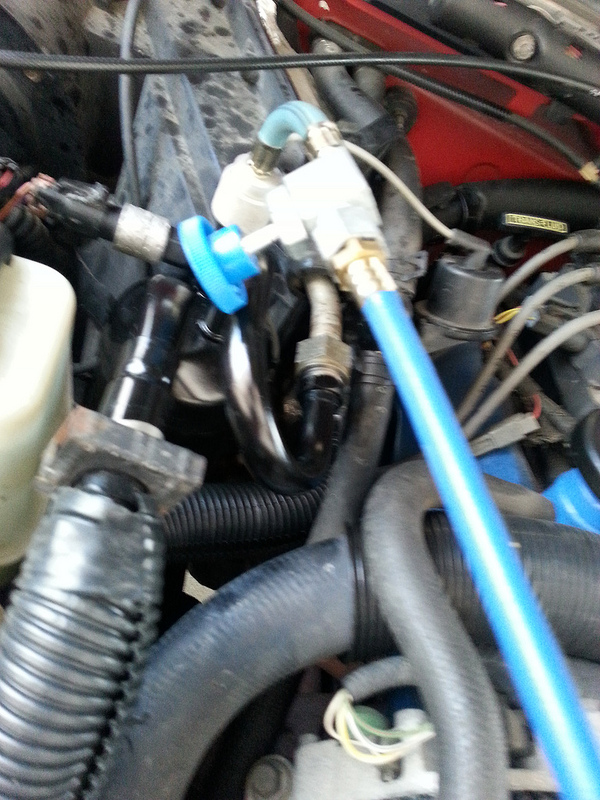
i. Claw upwards your manifold judge set. Blue to Low side (top of accumulator/ dryer) Red to High side (refrigerant line behind driver�south headlight) Brand sure all four of the valves are airtight.
2. Claw the vacuum pump to the yellow hose on the judge set. Make sure the valve on the pump is off.
3. Turn on the pump motor
4. Open all 4 valves on the approximate set up
5. Open up the valve on the pump.
6. Allow the vacuum run and the low side gauge (blue) should bear witness negative pressure. Allow it pump down to as close to a negative total atmosphere every bit you can (this varies depending on altitude, see nautical chart below) Normal atmospheric pressure is about 28 or 29 inches of Hg for people at 1000 to 1500 ft above sea level.
vii. If information technology is non pumping downwards, y'all have a pretty expert sized leak in your system somewhere.
viii. Later on it gets downwards to the proper vacuum level, allow the pump run for most ii hours. If information technology is very warm and/or boiling, allow it run longer. On an extremely hot and humid day, let it run for 4+ hours. Running it longer than 4+ certainly won�t injure. You can cut the time downwards on running the vacuum pump by starting the engine and letting it warm upwards to operating temperature. This will assist boil out whatsoever wet in the lines quicker. With the engine hot, your vacuum pull time will exist nearly an hour or so, 2 on the very hot and humid days. Once again running the vacuum longer won�t injure it.
*special note for atmospheric pressure/ vacuum and distance... The vacuum y'all will be able to pull will be directly related to your summit above sea level (meet chart below) Your atmospheric pressure level is lower every bit you get college in altitude. Please utilise this chart to calculate how much vacuum y'all should pull for your altitude:
Sea Level = -29.92 in-Hg
500 anxiety = -29.iv in-Hg
1000 feet = -28.ix in-Hg
1500 feet = -28.iii in-Hg
2000 feet = -27.8 in-Hg
3000 feet = -26.viii in-Hg
4000 feet = -25.8 in-Hg
5000 feet = -24.9 in-Hg
6000 feet = -24.0 in-Hg
7000 feet = -23.1 in-Hg
8000 feet = -22.two in-Hg
(Thank you 4x4 Junkie!)
9. After information technology has run for the required length of time, shut all 4 valves on the gauge set
ten. Shut the valve on the pump.
eleven. Turn off pump. Exercise non turn off the pump until the valve on the pump is closed.
12. Remove the pump from the gauge set and then remove the gauge ready from the car.
xiii. Replace the caps on the valves on the compressor.
14. Let the car sit down for about an hour or then. If you can, get out information technology sit overnight, this can permit you know if you take a slow leak.
15. After letting it sit, claw upward the manifold gauge set again. Open up the valve on the blue hose. Note the reading. Information technology should still have a -28 inches Hg vacuum. If it does not, you have a dull leak somewhere.
16. If y'all still have vacuum, Hook upward your vacuum pump and pull a vacuum for v to x minutes (just to be certain) and you lot tin now charge the system using Appendix C.
17. Remember to purge the xanthous hose with refrigerant first!
Y'all might be wondering why the vacuum needs to be practical for so long. This is to remove whatever excess moisture from the system. As the pressure decreases, the moisture will boil from the air easier and be pumped out. You lot may fifty-fifty see this on a actually humid twenty-four hours as the h2o spits out of the vacuum pump.
Letting the car sit is a skilful way to test for leaks without having to put refrigerant in, this mode you can fix them easier. Another protip given to me past 4x4Junkie is to start the truck and get it upward to temperature for several minutes earlier pulling the vacuum. this will allow the boiling off of the wet inside the system much quicker.


Appendix C
Charging the organization.
Tools you will need:
� Manifold gauge set for R134a automotive A/C Do not opt for the cheap unmarried gauge filler hose that hooks into the low side. You really need to monitor the pressure on both sides to properly fill and examination the system. If you do non have and cannot afford the manifold gauge fix, rent or borrow 1.
� Thermometer
� The advisable amount of refrigerant for your truck. (97 Ranger�due south require 1lb 9oz or 25 Oz.)
Go on in mind, the simply manner you can accurately put the right corporeality of refrigerant in is to evacuate the system and add the recommended amount of refrigerant and and then stop. (25 ounces in the case of 1997 Ranger) Unless yous have access to very expensive machines that can weigh and meter out the verbal amount needed you lot volition desire to keep a very shut heart on the force per unit area for both Low and High side, and the outside temperature and the inside the middle left nuance vent temperature to get you lot shut to the marking. Remember, if yous overcharge the system, you tin break some expensive parts. A piddling flake of info that might brand your life easier: i pound = 16 ounces. The common r134a can is 12 ounces. The sticker nether the hood is rated in pounds and ounces (my 97 calls for 1 lb and 9 oz)
Procedure:
1. Make certain all 4 valves are closed on the manifold guess set up.
two. Claw the blue quick connect to the low side valve on the compressor. (Peak of the Accumulator/ dryer)
3. Hook the red quick connect to the high side valve on the compressor. (Refrigerant line behind the commuter side headlight)
four. Hang the gauge set from the hood making certain that none of the hoses can contact the belts or fan.
5. Let the xanthous hose run from the gauge set then that it hangs over the bumper.
6. Take a can of refrigerant and put the tapping device/valve on the can and run the valve in to puncture the can. Go on the valve airtight.
seven. Attach the valve to the yellow hose.
8. Open the valve on the can
9. At the manifold end of the yellow hose, there should be a shrader valve to bleed off pressure. Open up the valve on the refrigerant can and accept a small screwdriver and depress the shrader valve until the refrigerant comes out of information technology. This purges the yellowish hose of any regular air and wet which you do not desire in the system.
x. If this is only a recharge or �acme off� SKIP to Footstep 14!!
11. With the truck off, open up both the blue and red valves on the hoses next to the trucks refrigerant lines.
12. Open up both valves on the manifold portion. This will allow refrigerant to equalize on both sides of the compressor.
thirteen. Close the low side manifold valve.
fourteen. Shut the High side Manifold valve. You must do this before going to the next footstep!!
xv. Start the truck, and with the A/C off, bank check the static pressure. To check the pressure, open both the blue and red valves on the hoses side by side to the car�due south refrigerant lines. DO NOT OPEN THE VALVES ON THE MANIFOLD PORTION!!! If information technology is above 70 psi, y'all should have enough Refrigerant to cycle the compressor. A rule of thumb, your static pressure level will be shut to the outside (ambient) temperature when y'all are checking it.
16. Put the A/C controls to Max A/C and the blower on the highest setting. Make sure the A/C switch is on.
17. Make sure the engine is running and A/C is on full blast.
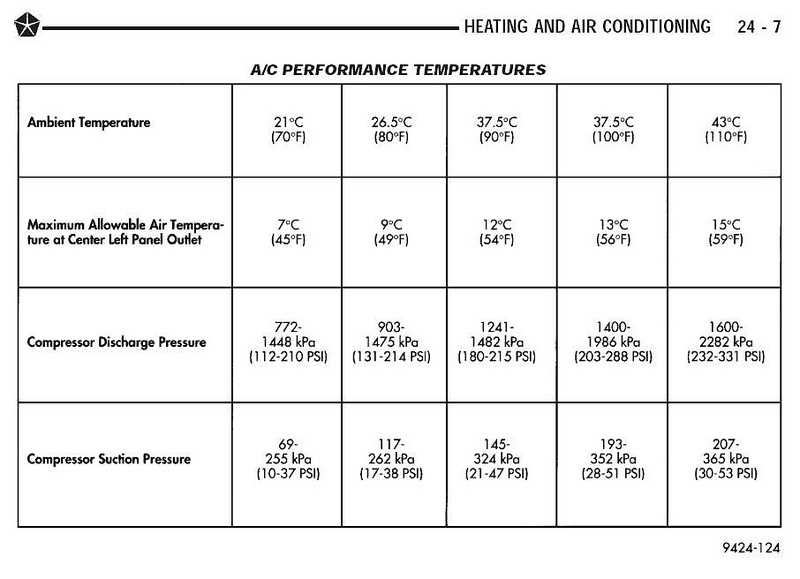
18. Await at the low side judge (bluish). It should read above 20 psi and below 55 psi depending on the temperature exterior at the time. Your high side guess (carmine) will exist in the range of 100 psi to 350 psi, depending on how hot information technology is outside. When the engine fan kicks in, your loftier side pressure volition drop quite a lot.
nineteen. If you are doing a fill with the exact amount of refrigerant (25 oz for a 97 Ranger) you may add the balance of the refrigerant now. 2 full 12 oz cans and a smidge of a third can total. Do not add whatsoever more than this!! (if your Ranger is a different year, please look up the proper amount for your truck)
20. For a tiptop off of a low charge organization, if your depression side pressure is below twenty psi, you tin add refrigerant to the system via the yellow hose. Pay close attending to the pressure temperature nautical chart when adding coolant. Something else to consider, if you are doing this on a cool day (below 65 degrees) you tin easily overcharge the organisation and not know information technology, so I would recommend charging information technology on a twenty-four hours that is warmer than 70 degrees. If your Loftier side pressure goes above 300 you lot are in danger of blowing out your condenser�
21. At present that y'all have the R134a can fastened and the valve open, open up the blueish manifold valve. Practise NOT Open up THE RED ONE UNDER Whatsoever CIRCUMSTANCE AS THE Loftier Pressure WILL CAUSE THE REFRIGERANT Can TO EXPLODE!! Opening the blue valve allows the refrigerant to be pulled into the depression side of the compressor to accuse the arrangement. Keep an eye on the gauges and charge the system until the low side is just under the low side pressure that correlates to the exterior temperature. The high side should not become much higher than 350 psi on a hot 24-hour interval. On a cooler day, both your low and high side pressures will be lower. If you empty your refrigerant can, turn off the blue valve on the manifold before unhooking the empty can. Be certain to purge the yellow hose again when you adhere the new can.
22. Protip: if you lot want the can of refrigerant to load a scrap faster, go a pan of hot tap h2o (no need to put it on the stove to heat it, straight hot water volition work) and dip the tin in it every bit information technology fills. This volition rut the refrigerant and brand information technology fill a fleck faster.
23. When yous reach the desired pressure and temperature settings (as confirmed by your pressure/ temp chart), you should have dainty cold air once again. Close the blue manifold valve, close the refrigerant tin valve (leave the can on the approximate set up. This manner you volition non have to purge it the side by side fourth dimension y'all utilize it�even if the can is empty, leave information technology on the gauge fix, it volition protect the yellow hose from getting contaminated with dirt.)
24. Your air temperature coming out of the middle vent in the dash should read as noted in the below table for the outside temperature listed. Since y'all cannot accurately measure out how much refrigerant is in the system and how much you lot have added, I would go on an center out on the temp pressure chart. In one case the vents become close to the temps listed, finish filling.
25. Close both valves at the refrigerant lines. Plough the engine off and release the quick connects. Warning: they will exist hot, especially the red or high side connection.
26. Replace the caps for the valves and put your tools abroad, you are done.


Appendix D
Troubleshooting
So let�s say that y'all have non led a make clean life and karma has caught upwardly to you and your truck needs more a recharge. I volition prove you how to replace the accumulator/dryer, the refrigerant lines, condenser and the compressor. This next section will be devoted to some simple troubleshooting to detect out what is wrong with the A/C.
The outset thing you want to practice is find out why your A/C is not working. Let�southward start with force per unit area. Does it hold a charge? If information technology is leaking, yous need to find where information technology is leaking at. Hither is how to look for leaks:
i. Following the steps above to recharge the system, put a leak detecting dye refrigerant can in the organization. Then afterward a week or whenever the organisation leaks out, get a UV calorie-free and find out where the leak is.
ii. Cheque the condenser thoroughly, especially looking for places where a rock could have damaged it.
three. Check the connections where the hoses claw into the components, and the compressor effectually the pulley, valves and hose connections.
four. Make sure the lines are not cracked or bent sharply.
If you have not found the leak in the engine compartment, you have probably accept a bad evaporator. It is inside the heater box.
Ok, then I accept a charged organization, and withal no cold air. What now, Einstein?
Well permit�s define �charged system�. For the A/C to work at that place must be effectually lxx psi static pressure in the system. If the pressure is beneath 70 or extremely high, the transducers will not send a signal to turn on the clutch. If you have pressure within the 40 to say nigh 70 psi static pressure range, your compressor should get-go. If it doesn�t starting time, check these areas:
1. Make sure the condenser is make clean and not chock-full with bugs, clay, minor animals, children etc..
ii. Also brand certain the fins are straight and permit air to laissez passer through. You lot can go a fin comb to straighten them out if needed.
three. Make sure all the fuses for the A/C compressor and blower are expert.
4. Check the relay for the compressor clutch. Y'all can do this past swapping it with other relays (Horn relay is a adept i to use)
five. Check to make certain all connectors are getting adept connection, peculiarly the clutch coil and Pressure transducer switch harness.
6. Have an ohmmeter and check for continuity on the clutch coil by unhooking the connector and checking for continuity between the terminals. If there is no continuity, your electromagnetic clutch is bad and will demand replaced.
seven. If all the above check out, you are left with a bad pressure transducer switch or wiring harness to the compressor or pressure switches.
And so we now know that information technology is charged, everything checks out mechanically and electrically. The compressor kicks in and turns, but it just does not put out cold air. Well, I hate to tell you this, merely your compressor is worn out and is not building pressure level on the refrigerant. Y'all volition need to replace the compressor. This can likewise be confirmed by the manifold approximate gear up. If the pressure differential between the loftier and depression side is very small, with typically fairly high low side pressure and depression high side pressure, the compressor is shot.
And then what say the compressor snaps belts or continuously squeals? The compressor is probably locked up; you volition need to replace the compressor.
Appendix E
Sources:
Flush or replace the condenser? http://www.aa1car.com/library/2003/us40330.htm
Flushing agents: http://www.acsource.com/brightsoluti...3832quart.aspx
http://www.amazon.com/Four-Seasons-6...sim_sbs_auto_1
Flush gun: http://www.amazon.com/Mastercool-910...sim_sbs_auto_2
Inline A/C filter: http://world wide web.autozone.com/autozone/par...er=946933_0_0_
Refrigerant and oil capacities for Ford vehicles: http://www.techchoiceparts.com/refri...ties/efgh#ford Notation: the values in this chart were different than what the sticker on my radiator support supplied for my truck, I went with the sticker�southward values.
General A/C Knowledge past TRS�south very own MAKG (from TRS Mag from June 04) http://www.therangerstation.com/Maga...une04/tech.htm This is an first-class source for those of you driving the older model Rangers, but much of the info provided carries over to the newer R134a equipped trucks.
Why become Double End Capped PAG oil instead of regular PAG Oil? http://www.autoactech.com/issues.htm
Expert all-around information: http://www.explorerforum.com/forums/...d.php?t=221950
Another nautical chart to confirm capacities: http://www.scribd.com/doc/48453503/p...application-05
Where I got my December PAG 46. Pretty good price too: https://www.ackits.com/pc/PCG46CT/Co...6+8+ounces+DYE
Where I got the Nylog: https://www.ackits.com/pc/RT201B/Nyl...or+HFC+Systems
Temperature and Pressure level reckoner: http://world wide web.csgnetwork.com/r134apresstempconv.html
Distance atmospheric pressure chart for calculating how much vacuum to pull:http://www.engineeringtoolbox.com/ai...ure-d_462.html
Thanks to:
4x4Junkie
Cvar
for their input in making this How-to more precise, easier to read and just all around better.
Hope this helps you get your A/C going over again.
AJ
Source: https://www.therangerstation.com/tech_library/Resurrecting_Your_Ford_Ranger_Air_Conditioning.shtml
0 Response to "1999 Ford Ranger a/c Stops Cooling Going Down the Road"
Postar um comentário